Figure 1: Nanocrystalline Nickel Film
1) I could find very limited documentation on the subject of Nanocrystalline Ni Film. In searching the internet I was only able to find one article on the subject. The article described the corrosion characteristics of the material. The article stated the following:
"The unique properties observed in recently developed nanocrystalline materials
can be useful or
applications such as advanced corrosion and wear resistant coatings, soft
magnetic materials for
magnetic recording, and elecrocatalysts for hydrogen evolution and oxidation
reactions."
The article goes on to describe in great detail how corrosion resistance of polycrystalline Ni is conserved in its electrodeposited bulk nanocrystalline counterpart.
Source: Corrosion Behavior of Electrodeposited Nanocrystalline Ni in Aqueous Environments.
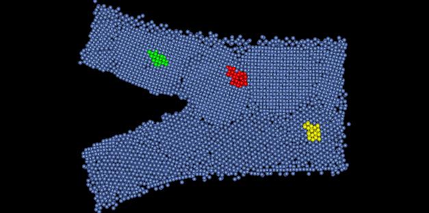
Perfect lattice nickel is has a crystal structure of FCC, and has a lattice parameter of 3.52 Angstroms. In this assignment we are looking at a computer simulated model on nanocrystalline nickel film. The model depicts the occurrence of a crack propagating through the structure. Figure 1 show the sample structure, with highlighted areas depicting the regions that will be examined further.
Figure 1: Nanocrystalline Nickel Film
2) The crystal structure of this material is hard to determine. Depending on where in the sample you look, the crystal exhibits different structures. At one place it appears to be a body centered cubic. Upon further inspection of this point however, the nanocrystalline nickel appears to be body centered triclinic. Figure 2 shows a dimensioned unit cell of the crystal from the yellow portion of Figure 1.
Figure 2: BCC appearing crystal structure
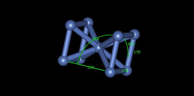
You can see that none of the crystal lattices or the angles are equal. This material is not really body centered. Portions of it only appear body centered because of dislocations in the material shifting the stacking layers. In another section of the material it appears to be face centered cubic. Figure 3 shows a dimensioned unit cell of the crystal from the green portion of Figure 1.
Figure 3: FCC crystal structure
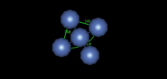
Although it may be difficult to make out in this image, the lattice parameter for this crystal is about 3.64 Angstroms, which is fairly close to the ideal parameter of 3.52 Angstroms. The unit cell shown here could be used well to model this material with symmetry.
3) There are several defects present in this model. The most common defects are grain boundaries. Figure 4 shows some grain boundaries present in this material located in red area of Figure 1.
Figure 4: Grain Boundaries
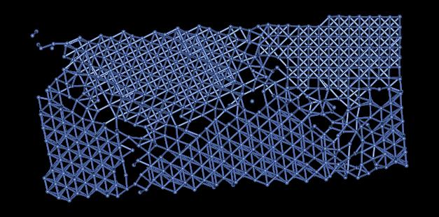
The many grain boundaries present in this sample greatly effect the symmetry of the material. Dislocations effecting the crystal structure preclude one from simulating this sample with periodicity. In addition to grain boundaries and dislocations, there are vacancies and free surfaces effecting the crystal structure of this material.
4) Figure 5 displays a grain boundary having an angle of approximately 14.3 degrees.
Figure 5: Grain Boundary Angle
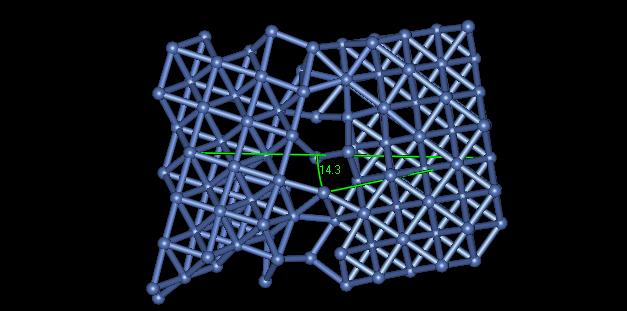
The angle of misalignment in this image is rather high. One can see that all of the atoms are not bonded together along the grain. The high angle grain boundary results in a higher local grain energy, but a lower total interfacial energy throughout the material.