Vacancies and Free Surfaces in BCC and FCC Iron
Justin Barker
ESM 4984
Introduction
Iron and iron alloys are some of the most common metals used in industry today. Iron alloys provide great strength and durability, but are also subject to corrosion. These caracteristics, along with the great availability of iron alloys, lend them to be used in many applications including the automotive, building and bridge construction, and aerospace industries. Most iron alloys are contain a certain amount of carbon, and are classified as steels. Pure iron is much weeker then its alloyed counterpart, and can be found in with two crystal structures. Ferrite is has a BCC crystal structure, and austenite has an FCC crystal structure.
In this exercise we are examining two types of defects common to this material, vacancies and planar defects. Vacancies are defects arising when a lattice site is mising an atom. They are caused by atomic vibrations present during the solidification of a material. The shell of atoms surrounding a vacancy will move in toward the vacancy, and the next shell of atoms will move out slightly. This relocation of atoms is termed relaxation. The planar defect examined here is a free surface. At the free surface of a material the atoms are not permitted to attach to the maximum number of atoms, resulting in an increased energy then found within the material. This energy is terms a surface energy.
BCC Vacancy
Lattice Parameter: 2.87 Angstroms
Cohesive Energy: 4.28 eV
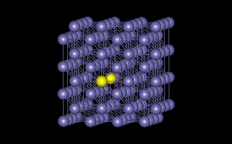
The model examined here contains 128 atoms, with one missing near the cnter of the structure. Periodic boundary conditions were used in all three directions. Figure 1 shows the vacant atom in the structure. The vacancy is located in between the two yellow atoms.
Figure 2 shows the plane containing the vacancy. The atoms surrounding the vacancy are shown in magenta.
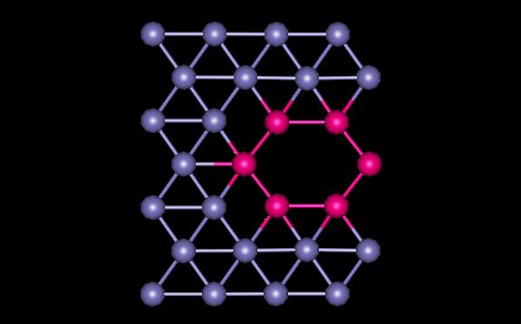
Figure 2: BCC Plane
The vacancy in the BCC structure yields the following energies and atomic displacements.
Minimum energy of the block after introducing the vacancy defect:
541.850 eV
Defect energy: 5.990 eV
Vacancy formation energy: 1.724 eV
Maximum atomic displacement after relaxation: 0.08377
Angstroms
Figure 3 shows the variations in interatomic distances at each shell away from the vacancy. You can see that the first shell moves in towards the vacancy, and the second shell moves away slightly.
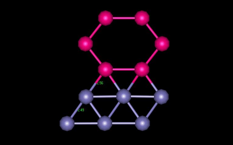
Figure 3: BCC Interatomic distances
FCC Vacancy
Lattice Parameter: 3.515 Angstroms
Cohesive Energy: 4.196 eV
The model examined here contains 256 atoms, with one missing near the cnter of the structure. Periodic boundary conditions were used in all three directions. Figure 4 shows the vacant atom in the structure. The vacancy is located in between the two yellow atoms.
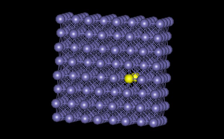
Figure 4: FCC vacancy
Figure 5 shows the plane containing the vacancy. The atoms surrounding the vacancy are shown in magenta.
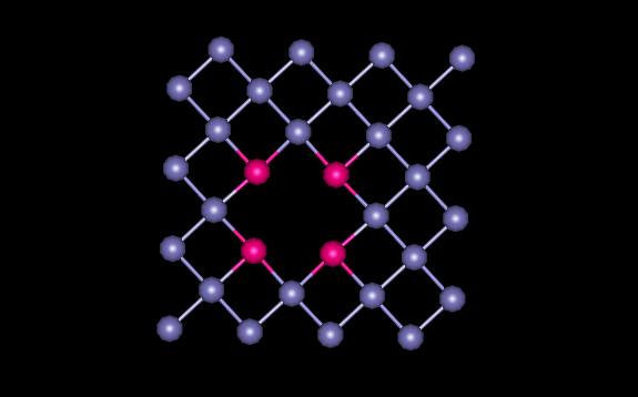
Figure 5: FCC Plane
The vacancy in the FCC structure yields the following energies and atomic displacements.
Minimum energy of the block after introducing the vacancy defect:
1068.311 eV
Defect energy: 5.856 eV
Vacancy formation energy: 1.672 eV
Maximum atomic displacement after relaxation: 0.03809
Angstroms
Figure 6 shows the variations in interatomic distances at each shell away from the vacancy. You can see that the first shell moves in towards the vacancy, and the second shell moves away slightly.
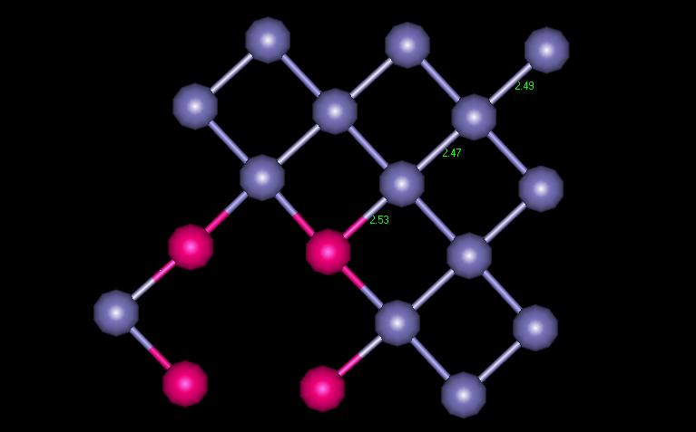
Figure 6: FCC Interatomic distances
The planar defect was created by forming a separation between atomic plates. I chose to model BCC iron in the [1 2 0] formation. The model was created using periodic boundary conditions in the x and z directions. Figure 7 shows the plane created with the free surface indicated in yellow.
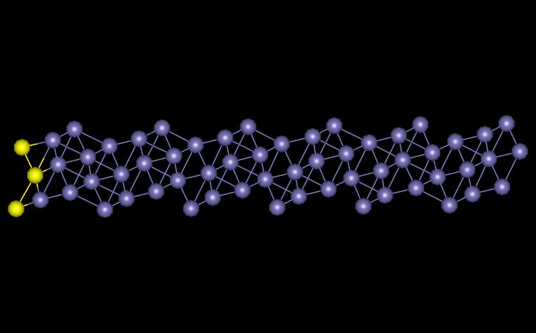
Figure 7: BCC [1 2 0]
The free surface in the BCC structure yields the following energies and atomic displacements.
Minimum energy of the block after introducing the vacancy defect:
601.034 eV
Free surface energy: 0.1548 eV
Maximum atomic displacement after relaxation: 0.25432
Angstroms
Figure 8 shows how the interatomic distances vary as you progress in from the free surface.
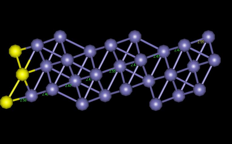
Figure 8: BCC [1 2 0] Interatomic Distances
The interatomic distances appear to be periodic as they migrate from the free surface. Figure 9 shows a chart of the periodicity.
Figure 9: Interatomic Chart
Callister, William D., Jr. Materials Science and Engineering an
Introduction. 4th ed. John
Wiley &
Sons: New York, 1997.