Generalized Plane Strain FEM Problem: NPIB
Submit batch job to compute stresses in a [0/90/45/-45]s "Type-II"
Graphite/Epoxy laminated composite plate without a ply-crack
Instructions for using this form:
- Enter appropriate numbers in the boxes,
- enter your email address,
- click on submit, and
- wait for results to be returned to your email.
(this will take about 20 seconds)
- Web location of results: pc4l.html will be sent to your email address.
- If your email does not provide direct email links, copy and paste the
web address: http://www.jwave.vt.edu/output/nc4l_"unique
date-time"/nc4l.html from the email into your web browser
Location: window and look at this file to see if the job ran correctly.
- If the job ran correctly you can now download files from your
web browser to your computer for archiving (a 4.6Gbyte read/write optical
disk is available for each student to use in the SMVC for archiving large
simulation files).
- If you submit the form "as-is", a sample of results has been archived in the directory:
http://www.jwave.rkriz.net/output/ARCHIVE_Examples_SAVE/nc4l_10-23-2000-8:38:28:231/
Select
nc4l.html
to see a summary of the results.
Below is a description of the laminate geometry and finite element grid representation
used to define the "4-Layer Without a Ply-Crack" problem. A detailed explanation of the
"4-Layer Ply-Crack" problem is given in Ref.[1],"Influence of Ply Cracks on Fracture
Strength of Graphite/Epoxy Laminates at 76K", ASTM STP836, (1984), describes an actual
application using this computer program for the reader. As a summary the figures below
shows the laminate stacking sequence, FEM grid, and stress distributions for this
specific problem.
Notice how all the stresses are influenced by thermal ("THERM")
and moisture ("MOIST") conditions supperposed with the mechanical ("MECH") load case.
These stress distributions are significantly influenced by the combination of residual
stresses caused by the thermal contraction at low temperatures, Delt-T=-180F, and swelling
caused by moisture absorption, Delt-M=1.2% moisture. Without a ply crack a direct
comparison can be made with the stress components predicted by thin laminated plate theory
that assumes the stresses with z components are very small. Hence SIGMA-Z, SIGMA-HZ and
SIGMA-NZ are assumed zero but a comparision of SIGMA-N, SIGMA-H, and SIGMA-NH is calculted
in module08 and shown in the table below.

Figure 1. Schematic of Laminate Geometry Showing Ply-Crack
Table 1. Comparison of Finite Element Model / Thin Laminated-Plate-Theory Ply Stresses (MPa)
| Layer |
sx |
sy |
txy |
| 0-deg |
4.99 / 5.09 |
574 / 577 |
0.15 / 0.0 |
| 90-deg |
-117 / -117 |
68.9 / 69.6 |
0.14 / 0.0 |
| +45-deg |
54.4 / 55.8 |
208 / 212 |
-94.6 / -96.5 |
| -45-deg |
54.2 / 55.8 |
208 / 212 |
94.2 / 96.5 |
Two-dimensional thin laminated-plate-theory stresses are caculated in
module08. Three-dimensional FEM Stress are calculated by
using the NPIB (Network Programming Interface Builder) form below match this particular
problem. Of course with the NPIB form a variety of other configurations are possible.
NOTE: We have provided a complete set of ELEMENT NUMBER GRIDS below so that
the student can calculate stress distributions different from the three graphs
shown above.
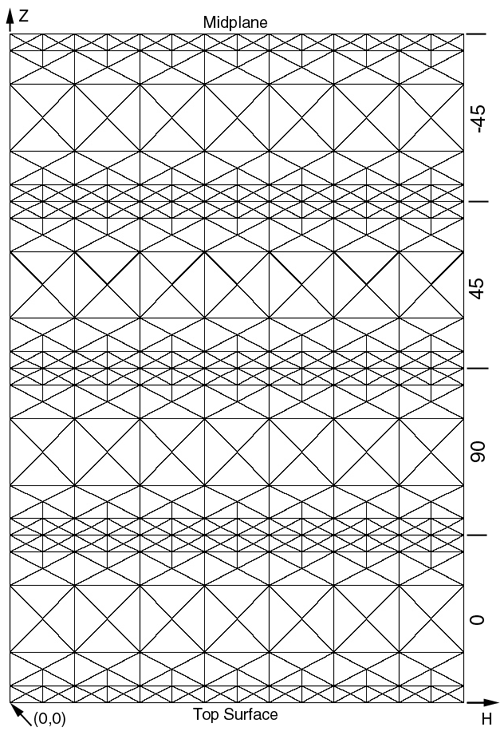
 Grid with Element Numbers
You might want to reproduce the results shown in th figures above using the form in the
frame provided below. You will also need to use the Linear Elastic Laminated Plate
Analysis (LELPA) program in "module08" which is used to
convert the Nx=1552 lb./in. into strains in the x and y directions. The strain
in the y-direction, calculated by LELPA, is then used as the out-of-plane strain normal
("N-direction") to the H-Z plane in the form below. The strain in the x-direction
("H-direction") is imposed by nodal displacements.


