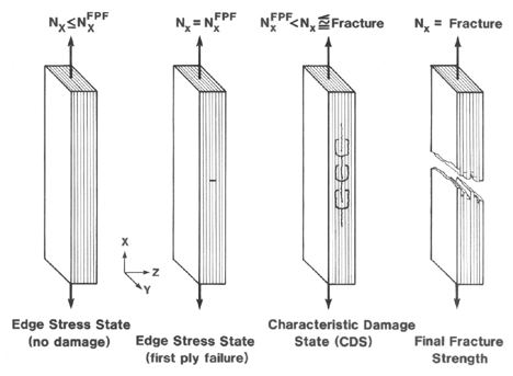
Figure 32. Typical sequence of damage events leading to laminate fracture
Ronald D. Kriz, Associate Professor
Engineering Science and Mechanics
Virginia Polytechnic Institute and State University
Blacksburg, Virginia 24061
Mechanical behavior of thick laminated plates can be accurately predicted by simple laminated plate theory, but the stresses within these thick laminates are not accurately predicted by classical laminated plate theory. For thick laminates stress singularities result in controlling the sequence of failure events that lead to the ultimate fracture of the laminate. Figure 32 shows a typical sequence of damage events that lead to ultimate fracture at the macroscale.

To accurately predict stress singularities in thick laminates we introduce the laminate "Free-Edge" problem. In this section we provide:
Below is a description of the laminate geometry and finite element grid representation used to define the stress "Free Edge" problem. The figure below shows the laminate stacking sequence and FEM grid for a specific problem in Ref.[21].
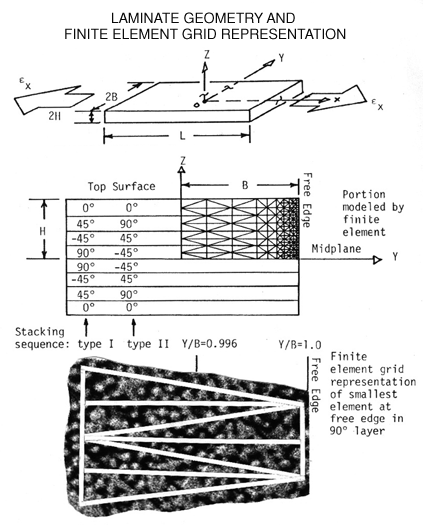
NOTE: the enlarged area showing the smallest element of the F.E.Model at the free edge is reaching the conceptual limit of the assumed homogeneous approximation ("continuum") for material properties in each element at the free edge. The finite element mesh superposed over a SEM photograph shows the heterogeneity of each graphite fiber diameter, 5 microns, is observed as a fuzzy white region. Here we are pushing the limit and assuming each element still behaves like a continuum with three fiber diameters in the z-direction and ten fiber diameters in the horizontal y-direction. For FEM elements smaller than this a continuum model can no longer be used. Instead a different model needs to be created at Y/B > 0.998 where mechanical behavior is now controlled by the individual fiber and matrix components. Hence the continuum approximation breaks down at this point.
Example of results prior to First-Ply-Failure (FPF) in the WET ("water saturated") condition, shown below, demonstrate the stress singularity of the stress distribution of the normal stress in the z-direction along each laminate interface. This singularity can only be accurately modeled up to Y/B=0.998 as a continuum.
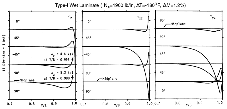
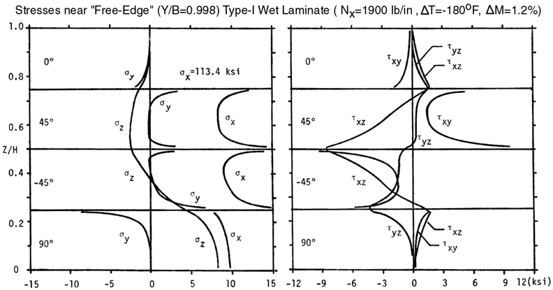
You might want to reproduce the results shown in this Figures 34 and 35 by going to the interactive computer program. You will also need to use the Laminated Plate Analysis program which is used to convert the Nx=1900 lb./in. to a strain in the x-direction. The strain in the x-direction, calculated by LELPA, is then used as the out-of-plane strain normal to the H-Z plane in the form below. Notice that the σz stress reverses and becomes negative ("compressive") along the +45/-45 interface and 0/+45 interface most likely because of the combination of residual stresses caused by the thermal contraction at low temperatures, ΔT=-180F, and swelling caused by moisture absorption, ΔM=1.2% moisture.
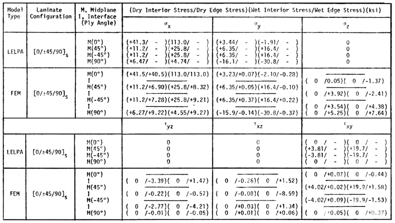
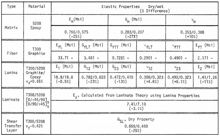
All stresses at the laminate stress free edge and interior are summarized below in Table 4. Elastic properties used to calculate these stresses are listed in Table 5.
In section 5.0 above a FEM model predicted stress free edge singularities in type-I quasi-isotropic laminate, Ref.[21]. In section 6.0 below a FEM model predicts stress singularities near a 90o ply crack terminating at the 0/90 interface in a type-II quasi-isotropic laminate, Ref.[1].