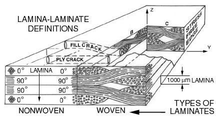
Figure 25. Lamina-Laminate Definitions
Ronald D. Kriz, Associate Professor
Engineering Science and Mechanics
Virginia Polytechnic Institute and State University
Blacksburg, Virginia 24061

In the previous section, 4.1 Introduction to Mechanical Behavior of Anisotropic Materials, mechanical behavior of individual anisotropic layers, "lamina", of the "laminated" plate can now be used to model the mechanical behavior of the laminate. The purpose of this section is to introduce the reader to the basic ideas of laminated plate theory so that the reader gains an understanding of the relationship between the two scales. To gain a working knowledge of laminated plate theory, we encourage students to take ESM4044 MECHANICS OF COMPOSITE MATERIALS and ESM6104 MECHANICS OF COMPOSITE STRENGTH AND LIFE . With a working knowledge of laminate plate theory, designers can taylor the elastic properties and orientation of each lamina, hence optimize their design by controlling the properties and orientations of each lamina. At the end of this section we will outline several examples on how the mechanical response of a laminated plate can be controlled ("designed") by lamina properties, but first we briefly outline the derivation of the analytic model needed to understand how properties at the microscale control mechanical behavior at the macroscale.
Analytic Model:
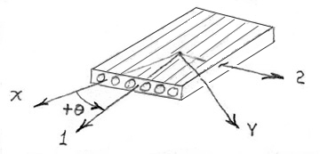
Consider an orthorhombic lamina in plane stress and let the 1-2 axes shown in Figure 26 be aligned with the fiber axis. In plane stress we assume the lamina is very thin and the stress through the lamina thickness is very small.
 |
(44) |
The elements of [Q] are related to the engineering constants E,G, and ν as follows
 |
(45) |
 |
(46) |
Transformation of lamina stress and strain from the 1-2 axes to the rotated x-y axes is shown here in matrix notation. This transformation is different from the transformation for all components of the second order tensor because here we have only three components of stress and strain because of the plane-stress condition.
 |
(47) |
where
 |
(48) |
The lamina stress-strain relationship in the rotated x-y coordinates
 |
(49) |
In reduced matrix notation
 |
(50) |
where
 |
(51) |
The inverse stress-stain relationship relates stresses(known) to strains(unknown) with the compliance, [S], matrix
 |
(52) |
where
 |
(53) |
Hence there is an inverse relationship between the [S] and [Q] matrices.
 |
(54) |
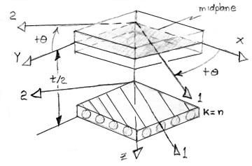
The equations above apply to each individual laminate layer ("lamina"). Next we stack each lamina into a laminate where we assume each lamina, denoted with a subscript k, is bonded ("glued") to the adjacent lamina. The composite structure is referred to as a laminated plate, see Figure 27.
The laminated plate shown in Figure 28 is loaded, in the Z-direction. Deflections are assumed small and the Kirchoff thin plate approximations can be used here to derive relationships between in-plane and out-of-plane displacements, curvatures, twists, and strains.
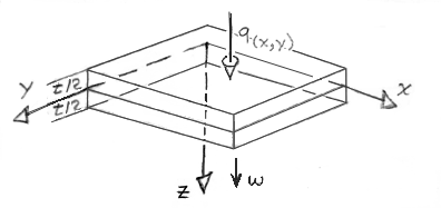
From Figure 28 it is not difficult to see how in-plane uo and vo displacements are augmented by out-of-plane (Z-direction) displacements and rotations.
 |
(55) |
From equation (7) the strain-displacement relationship are rewritten here for components of displacement, u and v, confined to the x-y plane ("in-plane").
 |
(56) |
From the expression of radius of curvature, ρ, we derive expressions for curvature, kx and ky assuming small angular deflections.
 |
(57) |
A similar expression for twist, kxy, can be derived from Figure 29 where twist is defined as an "angular change" per "unit length".
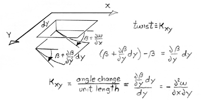
The coefficient of 2 is introduced by convention for engineering shear strain.
 |
(58) |
Combining equations (57) and (58), into (56) yields
 |
(59) |
Substituting equation (59) into equation (49) yields a more general stress-strain relationship for the k-th lamina which includes out-of-plane displacement implicitly in the curvature terms.
 |
(60) |
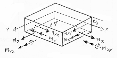
With stresses defined in terms of the Z-coordinate, through the laminate thickness, we integrate these expressions to get the laminate resultant in-plane loads (Nx, Ny, Nxy), and moments (Mx, My, Mxy).
 |
(61) |
Substitute equation (60) into equation (61) and simplify.
 |
(62) |
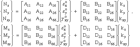
Equation (62) can be simplified
 |
(63) |
where
 |
(64) |
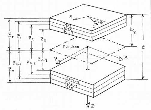
Figure 31 shows the relative position of each k-th lamina used by equation (61) to integrate through the thickness to calculate the laminate loads, (Nx, Ny, Nxy), and moments (Mx, My, Mxy).
Substituting the [A], [B], and [D] matrices defined in equation (64) into equation (63) results in the final relationship that defines the mechanical behavior of laminated fiber-reinforced plate. Equation (63) shows the relationship between known in-plane strains ( εox, εoy, γoxy ) and curvatures ( kx, ky, kxy ) and unknown in-plane loads and moments.
 |
(65) |
And the inverse relates known in-plane loads to unknown in-plane strains and curvatures.
 |
(66) |
The [A], [B], and [D] matrices for the laminate are similar to the [Q] matrix for the individual lamina. If you followed the basic ideas in this derivation it is not difficult to understand how microscale lamina properties control the macroscale laminate properties. In deed we now have a predictable way to control, and hence design, the mechanical behavior of a laminate at the macroscale.
Like the lamina at the microscale, anisotropy of the laminate has a significant effect on the mechanical behavior of the laminate. This can best be observed by inspection of equations (65) and (66). If the individual lamina are stacked and glued together such that the [B] matrix is zero then the mechanical behavior exhibits a decoupling of moments and in-plane loads. For example curvatures only affect moments and inplane strains only affect inplane load. On the other hand it is not difficult to see that if [B] is not zero then there is coupling between curvatures and inplane loads, and coupling also exists between inplane strains and moments. This is rather peculiar. For example if we apply an inplane strain to a specially configured laminate then the laminate can bend more then it would extend ("stretch"). Similarly if we apply an inplane load the laminate will twist. The later is actually used to an advantage by designers of aircraft structures where aircraft wings, that are constructed by fiber-reinforced laminates, are designed to twist into a predetermined aerodynamic angle-of-attack as the wing bends and extends. This design methodology is called PASSIVE aero-elastic tailoring. With "smart"-"intelligent" structures it is possible to insert active piezoelectric layers into the laminate stacking sequence and ACTIVELY control the mechanical behavior of the laminate. The degree of coupling is controlled by the [A], [B], and [D] matrices.
In this section a few simple examples are presented that illustrate how simple laminate configurations can provide predictable macroscopic mechanical behavior by inspection of equations (65) and (66).
By inspection when [B] is zero, inplane loads and moments decouple in
equations (65) and (66).
Inplane loads {N} only produce inplane strains {ε}
and inplane moments {M} only produce
curvature {k}
Bi-directional laminates consist only of 0/90 degree lamina.
It is not difficult to show Q16 and Q26
are zero. Hence A16 and A26 are also zero and consequently
the inplane shear strain {γ} decouples
from the inplane normal strains. Therefore shearing loads can only produce
shearing strains and
inplane normal loads can only produce inplane strains
For a large number of symmetric pairs, +θ
at +h and -θ at -h, D16 and D26
go to zero. Hence
moments {Mx} & {My} and torque {Mxy} decouple
so that bending caused by moments do not
introduce twisting and torque that causes twisting does not introduce bending.
Accept for a few simple cases outlined above, equations (65) and (66) are sufficiently complex where the designer can not deduce a solution by observation. These equations must be solved numerically, hence the designer must make educated guesses and experiment by submitting multiple jobs and hopefully converge on a particular design. To control the mechanical behavior of the laminate requires attention on controlling the [A], [B], and [C] matrices. For complex stacking sequences this becomes difficult. Many references on designing laminated structures exist. As an introduction we suggest the reader look at Refs.[19,20]. To that end we provide an interactive tool below that will allow the reader to experiment and design the desired laminate mechanical behavior.
In summary we have shown the significant role anisotropy has on the mechanical behavior of laminates both at the microscale and macroscale. The bridge between the microscale ("lamina") and the macroscale ("laminate") is accomplished with analytic models of laminated plate theory. In the theory of laminated plates we have ignored the stresses and strains in the z-direction (thin-plate assumption). For thicker laminates at the macroscale these stresses can not be ignored indeed these stresses are significant and cause the formation of ply-cracks, see Figures 1,3, and 4. In the next section we provide another model that predict stress singularities at the laminate free-edge. Singularities at the laminated free-edge are also largely influenced by anisotropy at the lamina microscale.